


Cutting Slots Form Effective Cutting Edges
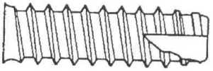
The cutting slots at the screw point or thread section create edges that perform a cutting action. As the screw is driven into the workpiece, these cutting edges progressively remove material from the hole wall and form internal threads that match the screw profile.
Cutting performance depends on the slot angle, cutting-edge condition, screw hardness, and workpiece material.
Suitable for Threading Harder Materials
Compared with thread-forming screws that primarily rely on plastic deformation of the material, TYPE-BT removes part of the workpiece material during installation, helping reduce forming pressure. This makes it more suitable for materials with limited ductility, higher hardness, or poor thread-forming characteristics.
Actual applicable hardness should still be confirmed according to screw material, heat treatment, and cutting capability.
Helps Reduce Driving Resistance
The cutting slots reduce the amount of direct material displacement required by the screw threads, allowing the screw to enter the pilot hole more easily and reducing the torque required from the fastening tool.
If the pilot hole is too small or the workpiece hardness exceeds the screw’s cutting capability, driving torque may still become excessively high.
Provides Space for Chip Accumulation
The cutting slots provide temporary space for chips generated during thread cutting, helping reduce jamming, scratching, or irregular driving caused by chips becoming trapped between the screw threads and hole wall.
For deep or blind holes, sufficient chip-clearance space should be provided, and an additional chip-removal process may be required when necessary.
Reduces the Need for Pre-Tapping
Once a properly sized pilot hole has been prepared, TYPE-BT can cut internal threads and complete the fastening operation directly, reducing the need for a separate tapping process.
May Eliminate the Need for a Separate Nut
TYPE-BT can engage directly with the internal threads it forms in the workpiece, making it suitable for applications where rear-side nut installation is difficult, one-sided assembly is required, or internal working space is limited.
Helps Improve Internal Thread Definition
With an appropriate cutting-edge design and pilot hole size, excess material can be progressively removed to create a more clearly defined internal thread profile. This is useful in assembly applications where driving torque and thread fit need to be controlled.
Actual internal thread quality should still be verified through cross-sectional inspection, torque testing, or pull-out testing.
Multiple Cutting-Slot Designs Available
Single-slot, double-slot, straight-slot, angled-slot, and other special cutting-slot structures can be selected according to workpiece material, cutting volume, chip-flow direction, and engagement depth.
Suitable for Blind Holes and Die-Cast Parts
TYPE-BT can be used in pre-drilled holes in aluminum alloys, zinc alloys, and other die-cast components. For blind-hole applications, hole depth and chip-clearance space should be confirmed to prevent chip accumulation from stopping the screw before full seating.
Simplifies Assembly and Machining Processes
TYPE-BT combines internal thread cutting and component fastening into a single operation, reducing separate tapping, cleaning, nut installation, and multi-component assembly processes.
Suitable for Automated Fastening
TYPE-BT screws with consistent specifications can be used with vibratory bowls, feeding tracks, and automatic screw-fastening equipment, making them suitable for high-volume production and assembly.
During automated fastening, rotational speed, downward force, driving torque, clamping torque, and chip conditions should be monitored.
Multiple Head Types and Surface Treatments Available
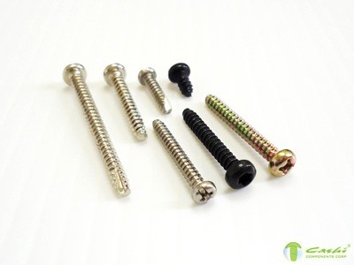
Depending on product appearance, installation tools, operating environment, and corrosion-resistance requirements, TYPE-BT can be produced with pan heads, countersunk heads, hex heads, and other head styles, together with different materials, heat treatments, and surface finishes.
Customization Based on Drawings and Samples
TYPE-BT screws can be customized according to customer engineering drawings or physical samples, including head type, drive recess, thread diameter, thread pitch, overall length, cutting-slot location, number of slots, slot width, slot depth, point structure, material, hardness, tolerances, and surface treatment.
Common Applications
TYPE-BT screws are commonly used in:
- Aluminum alloy and zinc alloy die-cast parts
- Metal enclosures, cabinets, and sheet metal structures
- Electronic and electrical equipment
- Automotive and motorcycle components
- Home appliances and consumer products
- Motors, fans, and mechanical components
- Telecommunications and information equipment
- Instruments and precision equipment
- Metal furniture and hardware accessories
- Rigid plastic housings and components
- One-sided assembly locations or areas where rear-side nut installation is difficult
- Mass-production and automated fastening lines
Key Considerations When Selecting TYPE-BT
Before selection, confirm whether the cutting slot is located at the screw point or along the thread section, and obtain complete information regarding the number, direction, width, depth, and length of the slots. Different cutting-slot designs may provide different cutting and chip-clearance performance.
Pilot hole size directly affects cutting performance. If the pilot hole is too small, cutting volume and driving torque may become excessively high, potentially causing screw breakage, cutting-edge wear, drive recess damage, or workpiece cracking. If the pilot hole is too large, thread engagement may be insufficient, resulting in thread stripping or reduced pull-out strength.
The screw surface hardness should be higher than the workpiece material in order to maintain effective cutting edges, while the core should retain sufficient toughness to reduce the risk of brittle fracture or torsional breakage during installation.
Because thread-cutting self-tapping screws generate chips, they may not be suitable for sealed electronic equipment, optical equipment, or high-cleanliness assemblies where foreign particles or metal chips are unacceptable, unless the assembly can be thoroughly cleaned afterward.
For blind-hole applications, adequate space should be provided between the screw point, accumulated chips, and the bottom of the hole. If the hole is too shallow, chip accumulation may cause a sudden increase in driving torque, prevent full screw seating, or damage the bottom of the hole.
Fastening tools should be set to appropriate rotational speed, downward force, and shut-off torque. Excessive speed may overheat or wear the cutting edges, while insufficient speed or downward force may prevent stable cutting engagement.
Whether TYPE-BT can be reused after removal should be determined according to cutting-edge wear, the condition of the internal threads in the workpiece, and the torque required for reinstallation. For products requiring frequent maintenance, pre-tapped holes with machine screws may be a more suitable option.
Before mass production, driving torque, tightening torque, failure torque, pull-out strength, chip condition, and internal thread integrity should be tested to confirm that the selected pilot hole, thread profile, and fastening parameters provide an adequate process safety margin.


